JFET distortion in a tuna can
A JFET distortion guitar pedal, based on the Fetzer Valve design from runoffgroove.com
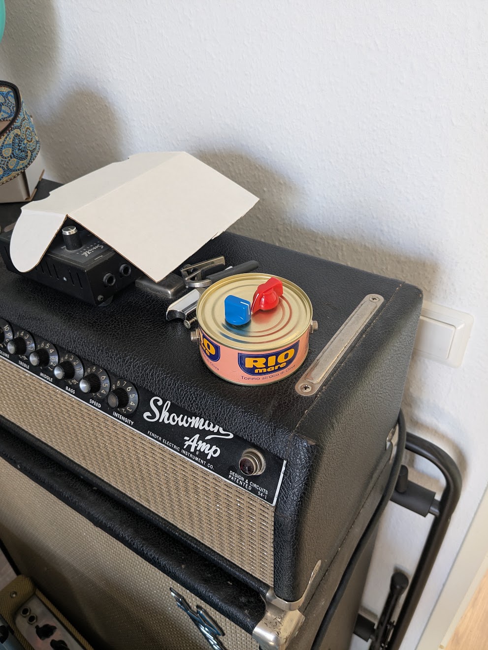
JFET distortion in a can
I've always loved simple DIY solutions, so when I was designing a distortion pedal while eating a tuna sandwich, it struck me that the can the fish came in would be the perfect cheap and fun enclosure. This prototype doesn't have a footswitch, and I didn't think to save the lid (which was bent anyway!), so it's open at the bottom, but it works, and it sounds good too. Maybe the leftover fish oils add to the fatty, saturated tone when the pedal is cranked? Maybe not.
The circuit is based on the Fetzer Valve from runoffgroove.com: a JFET-based emulation of the first gain stage of a Fender tube amp. I'm the lucky owner of a '65 Fender Showman, and while I know there's no substitute for a real tube amp, I was intrigued by the idea of a solid-state homage in 9V pedal format.
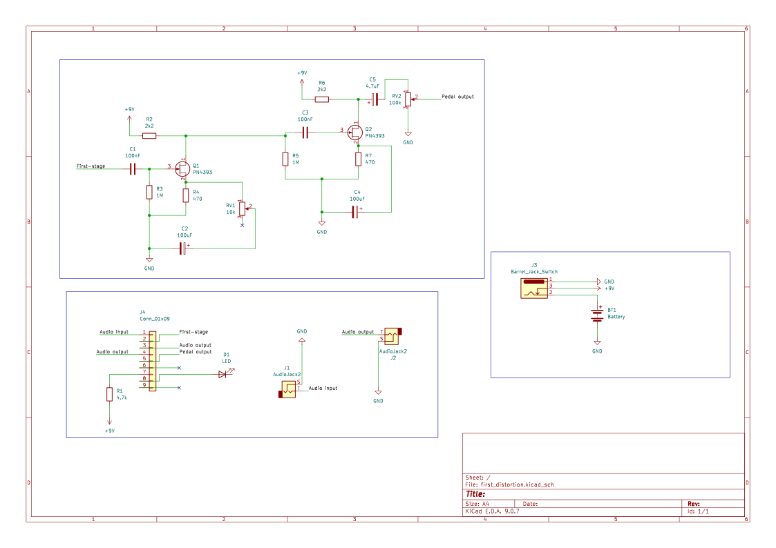
The original Fetzer Valve is deliberately a clean preamp emulation: it barely distorts on its own. So I stacked a second, identical JFET stage after the first one and added a pot between them to control the amount of distortion. Two Fender amp stages in a row, in other words. I used parts that I had lying around in my component box.
Here's the schematic, drawn in KiCad. I'm not a professional electronics engineer, so forgive me if it's a bit sloppy.
Biasing
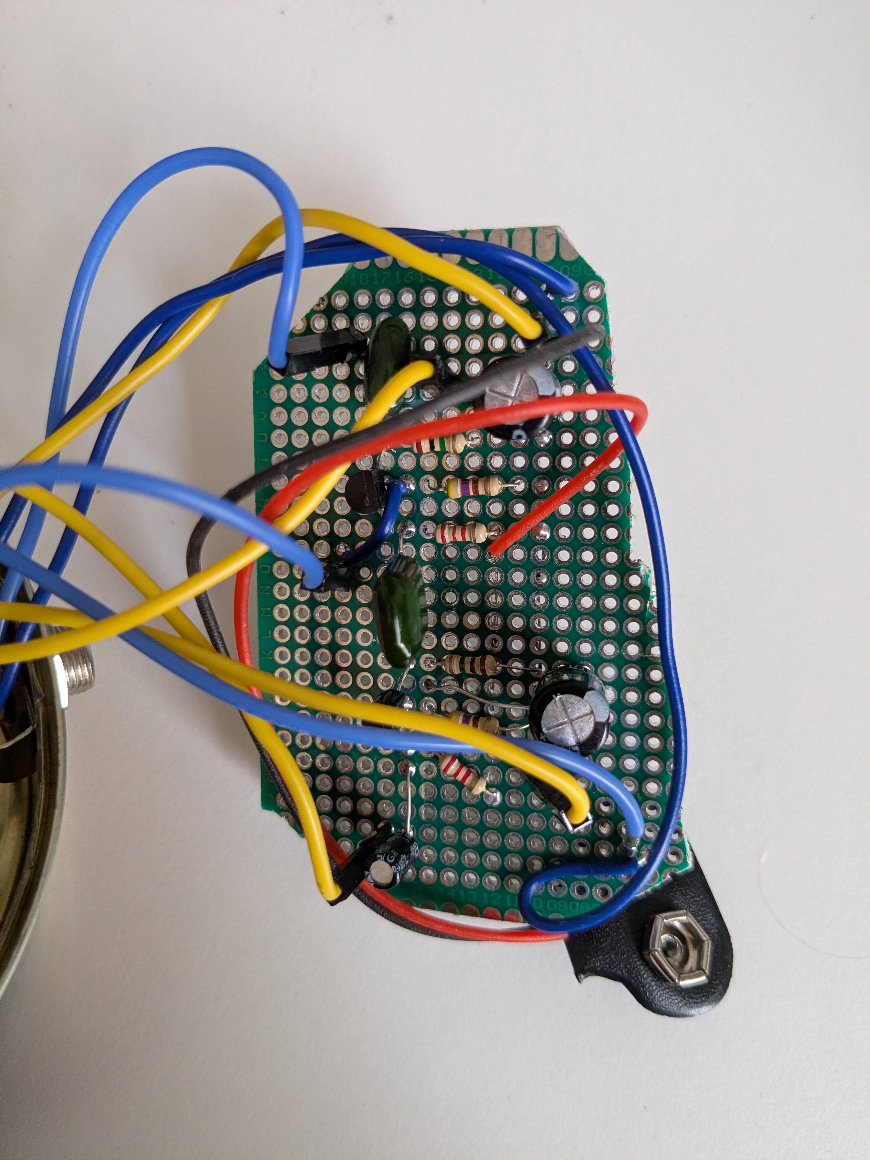
The hardest part of any JFET circuit is biasing. JFET parameters vary wildly from one individual device to the next (two transistors with the same part number can behave quite differently), so you can't just copy resistor values from a schematic and expect them to work. The goal is to get the drain voltage to sit around half the supply voltage (roughly 4.5V on a 9V battery), which gives the signal maximum headroom before it clips. In practice that means measuring the drain voltage and adjusting the drain resistor until it lands in the right spot. The values in my schematic are what worked for my JFETs. In my parts box, I only had linear potentiometers, not audio-tapered (logarithmic) ones. A linear pot feels like it does almost nothing until the last bit of its travel. It still gives enough control over the distortion amount, but it's not ideal. I also only put the pot on the first stage; you could add a second one (or rewire this one) to control the second stage too.
Measuring output level
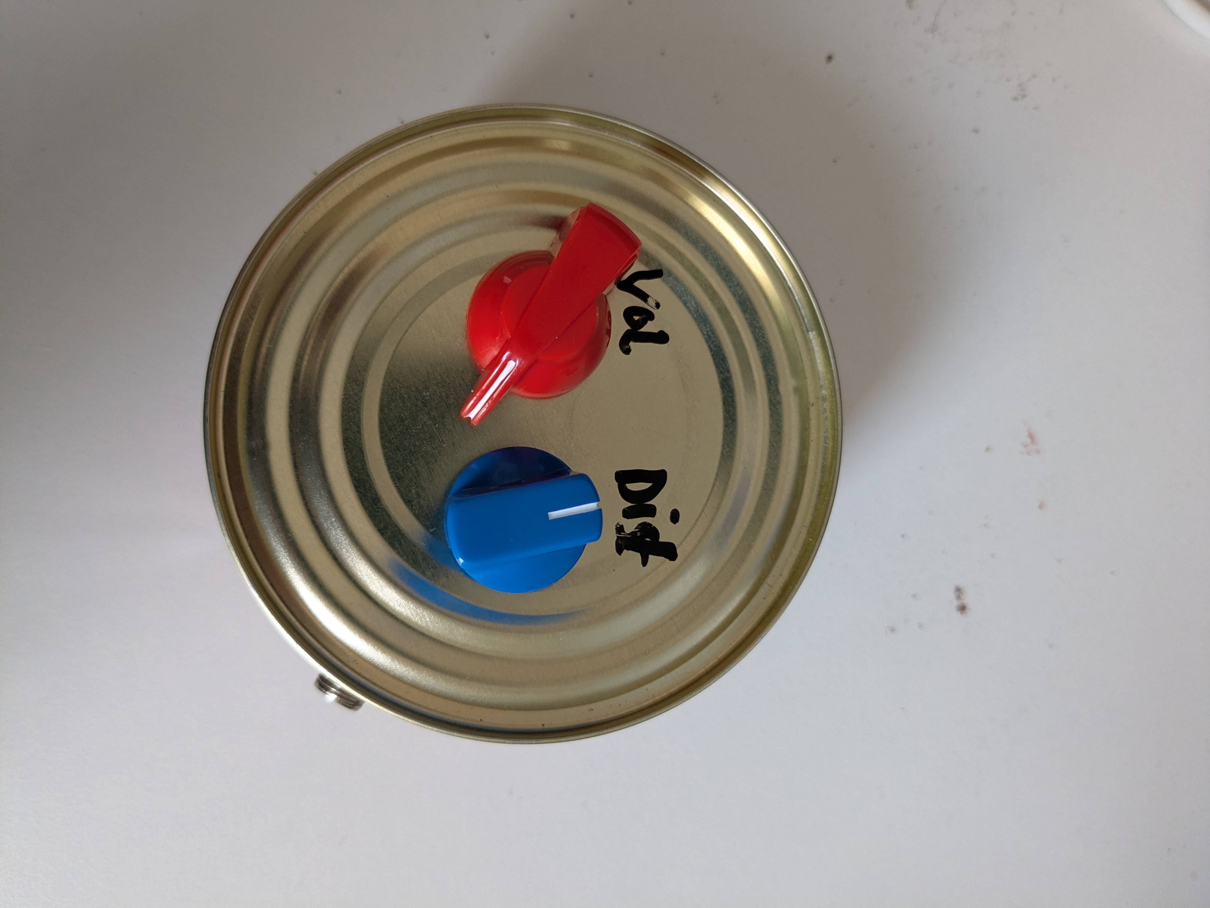
One thing I quickly noticed was that the output of this pedal is loud. That makes sense, since it's emulating the input gain stage of an amplifier, but I wanted to see just how loud. Cranked all the way up, my oscilloscope read something like 8.68 Vpp at the output. For reference, a guitar pickup typically puts out somewhere around 0.2 Vpp. For a distortion pedal that doubles as a boost, that's actually fine, but ideally unity gain (where the volume is roughly the same with the pedal on or off) would sit around the middle of the pot's rather than near the bottom. Another point for the audio-tapered pot, and something I'll try in the next revision.
Here's what it sounds like
Here's a guitar part for a song I recorded a while ago, through the '65 Showman with the pedal in front. Like a tuna, slicing through the water! Here it is with low distortion:
And with the distortion turned all the way up:
So you can definitely hear the signal is being quite heavily limited by the pedal in that last recording, which I kind of like. It's because the first JFET stage slams into the second one, which is effectively the same as chaining guitar amp stages in series. Having another control for the second JFET stage might be a good idea for the next revision!